 GL Tube-Type Furnace
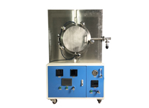
 XL Box-Type Furnace
 XQL Atmosphere Furnaces
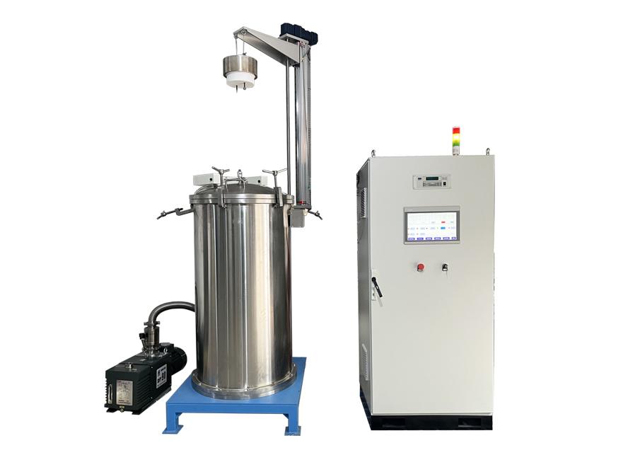 JSL Pit-Type Furnace
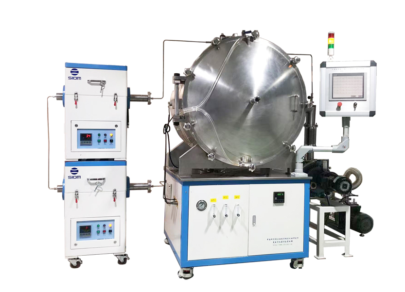 SJ Sintering Furnace
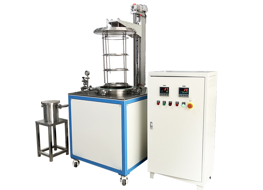 SJL Elevator Type Furnace